- 您现在的位置:买卖IC网 > Sheet目录287 > 24LC21-I/P (Microchip Technology)IC EEPROM 1KBIT 400KHZ 8DIP
�� �
�
�24LC21�
�3.0�
�BIDIRECTIONAL� MODE�
�3.1�
�Bidirectional� Mode� Bus�
�The� 24LC21� can� be� switched� into� the� Bidirectional�
�mode� (see� Figure� 3-1)� by� applying� a� valid� high-to-low�
�transition� on� the� Bidirectional� mode� clock� (SCL).� When�
�the� device� has� been� switched� into� the� Bidirectional�
�mode,� the� V� CLK� input� is� disregarded,� with� the� exception�
�that� a� logic� high� level� is� required� to� enable� write� capa-�
�bility.� This� mode� supports� a� two� wire� bidirectional� data�
�transmission� protocol.� In� this� protocol,� a� device� that�
�sends� data� on� the� bus� is� defined� to� be� the� transmitter,�
�and� a� device� that� receives� data� from� the� bus� is� defined�
�to� be� the� receiver.� The� bus� must� be� controlled� by� a�
�master� device� that� generates� the� Bidirectional� mode�
�Characteristics�
�The� following� bus� protocol� has� been� defined:�
�?� Data� transfer� may� be� initiated� only� when� the� bus�
�is� not� busy.�
�?� During� data� transfer,� the� data� line� must� remain�
�stable� whenever� the� clock� line� is� high.� Changes� in�
�the� data� line� while� the� clock� line� is� high� will� be�
�interpreted� as� a� Start� or� Stop� condition.�
�Accordingly,� the� following� bus� conditions� have� been�
�defined� (see� Figure� 3-2).�
�clock� (SCL),� controls� access� to� the� bus� and� generates�
�3.1.1�
�BUS� NOT� BUSY� (A)�
�the� Start� and� Stop� conditions,� while� the� 24LC21� acts� as�
�the� slave.� Both� master� and� slave� can� operate� as�
�Both� data� and� clock� lines� remain� high.�
�transmitter� or� receiver,� but� the� master� device�
�3.1.2�
�START� DATA� TRANSFER� (B)�
�determines� which� mode� is� activated.�
�A� high-to-low� transition� of� the� SDA� line� while� the� clock�
�(SCL)� is� high� determines� a� Start� condition.� All�
�commands� must� be� preceded� by� a� Start� condition.�
�3.1.3�
�STOP� DATA� TRANSFER� (C)�
�A� low-to-high� transition� of� the� SDA� line� while� the� clock�
�(SCL)� is� high� determines� a� Stop� condition.� All�
�operations� must� be� ended� with� a� Stop� condition.�
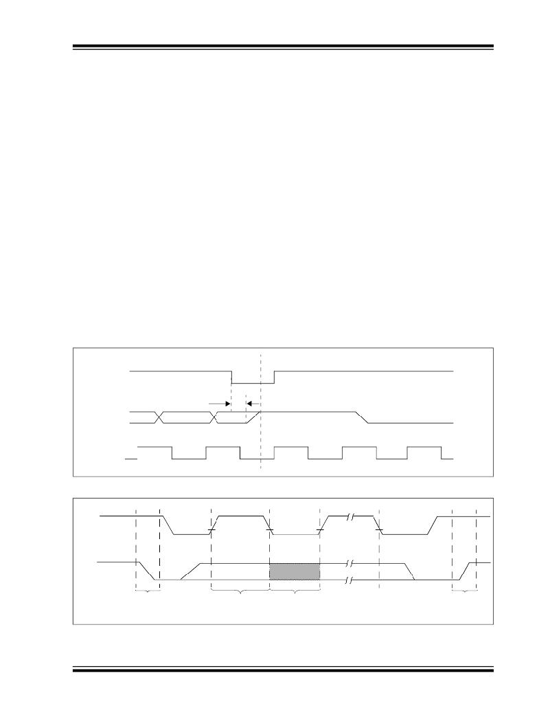
�FIGURE� 3-1:�
�MODE� TRANSITION�
�SCL�
�SDA�
�V� CLK�
�Transmit-only� mode�
�T� VHZ�
�Bidirectional� mode�
�FIGURE� 3-2:�
�DATA� TRANSFER� SEQUENCE� ON� THE� SERIAL� BUS�
�SCL�
�(A)�
�(B)�
�(D)�
�(D)�
�(C)�
�(A)�
�SDA�
�Start�
�Condition�
�Address� or�
�Acknowledge�
�Data�
�Allowed�
�Stop�
�Condition�
�?� 2004� Microchip� Technology� Inc.�
�Valid�
�to� Change�
�DS21095J-page� 5�
�发布紧急采购,3分钟左右您将得到回复。
相关PDF资料
24LC21A/P
IC EEPROM 1KBIT 400KHZ 8DIP
24LC22A-I/P
IC EEPROM 2KBIT 400KHZ 8DIP
24LC64XT-I/ST
IC SERIAL EEPROM 64K 2.5V 8TSSOP
24LCS21A/P
IC EEPROM 1KBIT 400KHZ 8DIP
24LCS22A-I/P
IC EEPROM 2KBIT 400KHZ 8DIP
24VL014/SN
IC EEPROM 1KBIT 400KHZ 8SOIC
24VL014H/SN
IC EEPROM 1KBIT 400KHZ 8SOIC
24VL024/SN
IC EEPROM 2KBIT 400KHZ 8SOIC
相关代理商/技术参数
24LC21-I/SN
功能描述:电可擦除可编程只读存储器 2.5V Dual Mode RoHS:否 制造商:Atmel 存储容量:2 Kbit 组织:256 B x 8 数据保留:100 yr 最大时钟频率:1000 KHz 最大工作电流:6 uA 工作电源电压:1.7 V to 5.5 V 最大工作温度:+ 85 C 安装风格:SMD/SMT 封装 / 箱体:SOIC-8
24LC21T/SN
功能描述:电可擦除可编程只读存储器 2.5V Dual Mode RoHS:否 制造商:Atmel 存储容量:2 Kbit 组织:256 B x 8 数据保留:100 yr 最大时钟频率:1000 KHz 最大工作电流:6 uA 工作电源电压:1.7 V to 5.5 V 最大工作温度:+ 85 C 安装风格:SMD/SMT 封装 / 箱体:SOIC-8
24LC21T-I/SN
功能描述:电可擦除可编程只读存储器 2.5V Dual Mode RoHS:否 制造商:Atmel 存储容量:2 Kbit 组织:256 B x 8 数据保留:100 yr 最大时钟频率:1000 KHz 最大工作电流:6 uA 工作电源电压:1.7 V to 5.5 V 最大工作温度:+ 85 C 安装风格:SMD/SMT 封装 / 箱体:SOIC-8
24LC22A-I/P
功能描述:电可擦除可编程只读存储器 VESA E-EDID RoHS:否 制造商:Atmel 存储容量:2 Kbit 组织:256 B x 8 数据保留:100 yr 最大时钟频率:1000 KHz 最大工作电流:6 uA 工作电源电压:1.7 V to 5.5 V 最大工作温度:+ 85 C 安装风格:SMD/SMT 封装 / 箱体:SOIC-8
24LC22A-I/PG
功能描述:电可擦除可编程只读存储器 VESA E-EDID Lead Free Package
RoHS:否 制造商:Atmel 存储容量:2 Kbit 组织:256 B x 8 数据保留:100 yr 最大时钟频率:1000 KHz 最大工作电流:6 uA 工作电源电压:1.7 V to 5.5 V 最大工作温度:+ 85 C 安装风格:SMD/SMT 封装 / 箱体:SOIC-8
24LC22A-I/SN
功能描述:电可擦除可编程只读存储器 VESA E-EDID RoHS:否 制造商:Atmel 存储容量:2 Kbit 组织:256 B x 8 数据保留:100 yr 最大时钟频率:1000 KHz 最大工作电流:6 uA 工作电源电压:1.7 V to 5.5 V 最大工作温度:+ 85 C 安装风格:SMD/SMT 封装 / 箱体:SOIC-8
24LC22A-I/SNG
功能描述:电可擦除可编程只读存储器 VESA E-EDID Lead Free Package
RoHS:否 制造商:Atmel 存储容量:2 Kbit 组织:256 B x 8 数据保留:100 yr 最大时钟频率:1000 KHz 最大工作电流:6 uA 工作电源电压:1.7 V to 5.5 V 最大工作温度:+ 85 C 安装风格:SMD/SMT 封装 / 箱体:SOIC-8
24LC22AT-I/SN
功能描述:电可擦除可编程只读存储器 VESA E-EDID RoHS:否 制造商:Atmel 存储容量:2 Kbit 组织:256 B x 8 数据保留:100 yr 最大时钟频率:1000 KHz 最大工作电流:6 uA 工作电源电压:1.7 V to 5.5 V 最大工作温度:+ 85 C 安装风格:SMD/SMT 封装 / 箱体:SOIC-8